Lorem ipsum dolor sit amet, consectetur adipiscing elit. Ut elit tellus, luctus nec ullamcorper mattis, pulvinar dapibus leo.
CASE STUDY -> INDUSTRIAL AUTOMATION
A purpose-built, PLC-controlled test system designed and delivered for Caterpillar Inc. in partnership with Tata Technologies — replicating real vehicle dynamic movements across three independent assemblies to flex-test EV cables under programmed oscillation, rotation, and translation cycles that simulate true field conditions.
01 — Project Context
EV charging cables routed through working vehicles are subject to continuous mechanical stress — oscillation, rotation, and translation — at every articulation point across the machine’s service life. This system was built to accelerate and quantify that fatigue in a controlled, repeatable, and fully automated test environment.
3
Bucket Flex, Hitch Flex, and Combined Axle Flex — each replicating the distinct motion profile of a different cable attachment point on the vehicle. Each assembly is independently servo-driven and recipe-controlled.
5
Bucket rotation, Hitch rotation, Axle X rotation, Axle Y translation, and Axle Z translation — all operating under Sinamics S200 drives coordinated by the Simatic S7-1500T CPU, with real-time position and velocity feedback on the HMI.
7
Bucket Flex, Hitch Flex, Bucket+Hitch combined, Axle X, Axle Y, Axle Z, and Axle X+Y+Z. Parallel tests can be run simultaneously — one from each assembly group — for efficient multi-cable qualification in a single cycle
10
The system stores up to 10 independent parameter recipes per test type. Each recipe defines positive position, negative position, and oscillation rate — bounded by machine limits with out-of-range error generation.
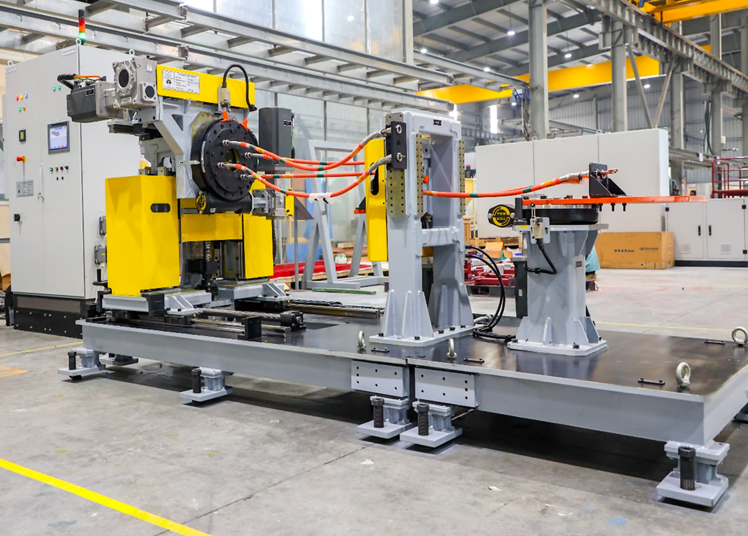
02 — System Overview
The three assemblies are mounted on a common base frame, each independently operated with servo drives, safety-rated limit switches, and mechanical overtravel stops. The full system is enclosed within a safety fencing structure with an interlocked access door.
03 — System Components
Each assembly mimics a specific motion at a distinct cable routing point on the vehicle. All three can operate simultaneously depending on the test configuration selected.
Assembly A
Replicates the oscillation experienced at the cable attachment point in the vehicle’s bucket. A slew drive rotates the modular mounting plate in both positive and negative directions, driven by a servo motor.
±15° to ±45° Oscillation
3.5 kW Servo
Slew Drive
Assembly B
Replicates the tighter articulation angle at the vehicle’s hitch point. A rotating bracket holds the cable and can be adjusted using bracket slots to set the required cable tension before the test cycle.
±3° to ±9° Oscillation
3.5 kW Servo
Slew Drive
Assembly C
The most complex assembly — three independent motion axes operating simultaneously or individually. Simulates the combined rotational and translational movement at the vehicle axle for the most mechanically demanding cable routing scenario.
X: ±3°–9° Rotation / 7 kW
Y: ±100 mm / 5 kW
Z: ±100 mm / 7 kW
Overtravel protection: Every axis is protected by a two-layer safety system — software-enforced limit switches trigger an alarm and stop the axis, and a second set of physical mechanical stoppers provides a hard boundary as a redundant safety layer. Each axis has its own independent limit switch pair.
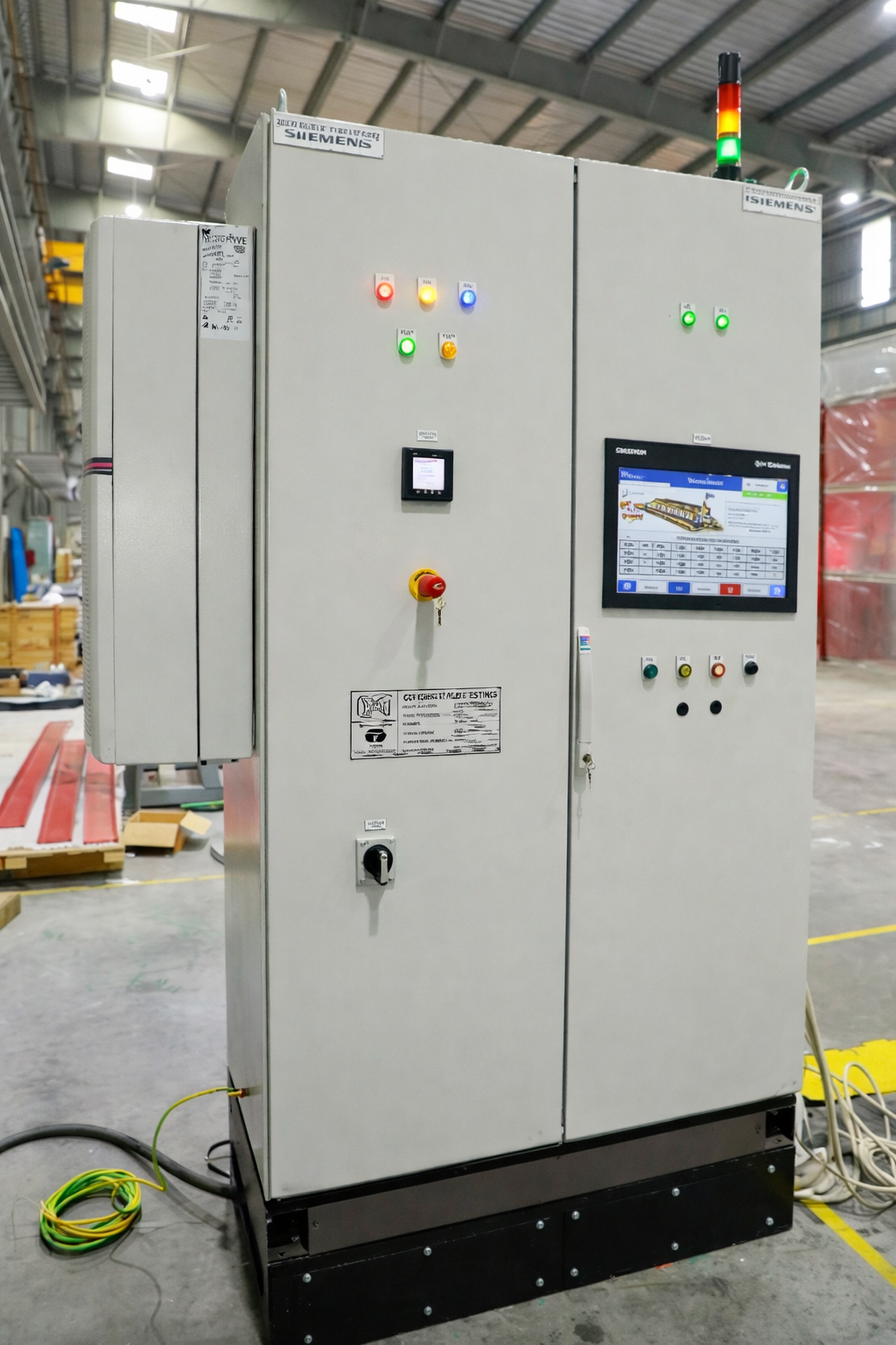
04 — Control Architecture
The system is controlled by a Siemens Simatic S7-1500T CPU — Siemens’ motion-optimised PLC — coordinating five servo drives over PROFINET. All drives, the HMI, the IM module, and the energy meter are connected via an Ethernet switch on the same network segment, with individual IP addresses monitored live from the System Architecture screen.
The Simatic TP1200 Comfort Panel (12″ touchscreen HMI) provides the full operator interface: login management, recipe configuration, flex type selection, live cycle monitoring, alarm display, drive status, and manual axis jogging. All screens are access-controlled by user role — Operator, Supervisor, or Maintenance.
The Pilz safety relay monitors the overall safety circuit including both emergency stops and the door interlock, ensuring a hardware-level safety layer that operates independently of the PLC logic.
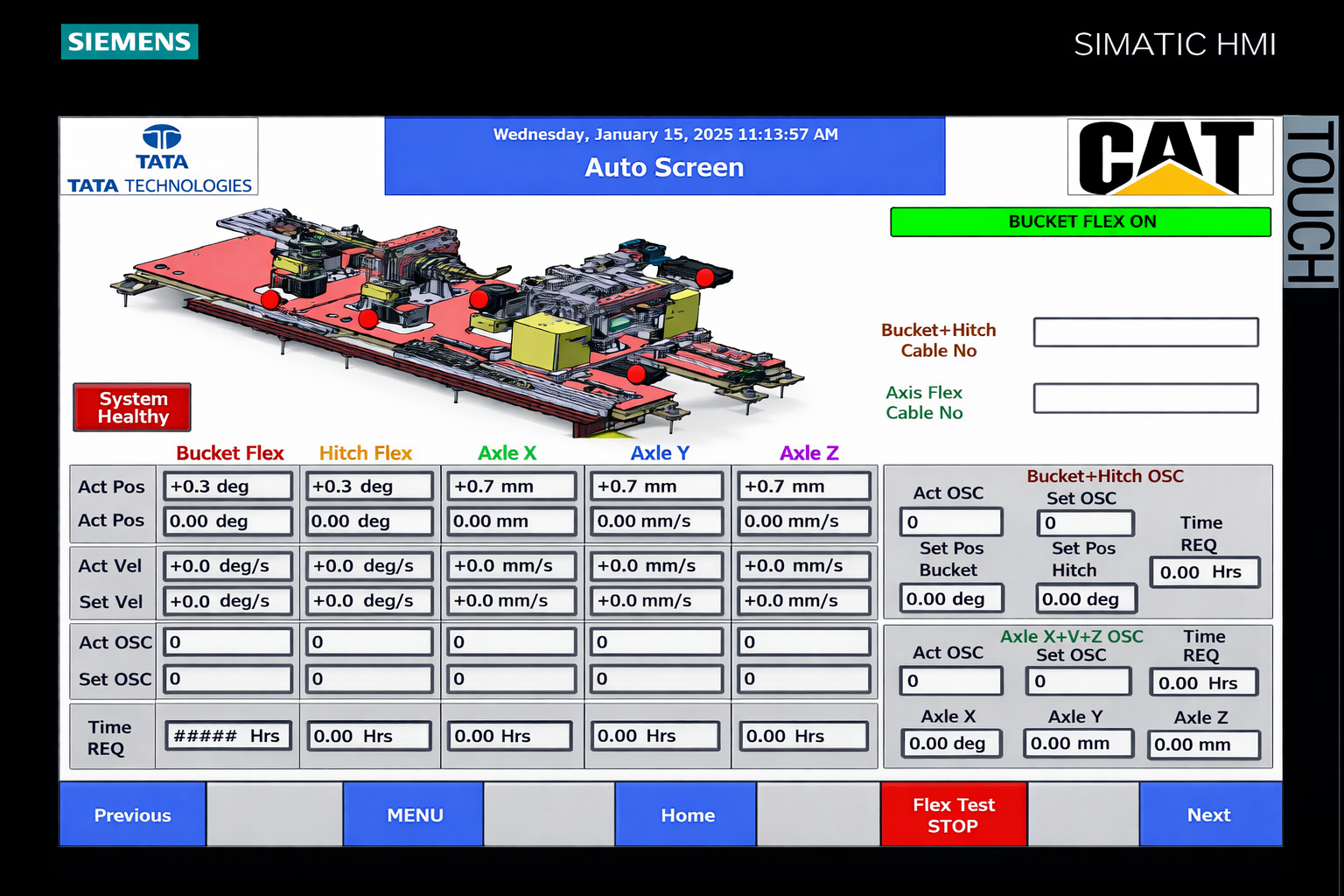
05 — Test Execution
The system operates in Auto Mode for production testing and Manual Mode for setup and maintenance. Both modes require the selector switch on the main panel and the teach pendant to match — neither activates unless both are in agreement.
1
Supervisor logs in via HMI and sets test recipes — defining positive position, negative position, and oscillations per minute for each flex type. Up to 10 recipes per test type. Out-of-bounds values generate an error.
2
Operator mounts the test cable on the rig. Operator selects the required flex test type(s) from the Flex Selection screen — one from each assembly group for parallel operation.
3
Operator physically acknowledges three pre-start conditions on the HMI. The machine verifies the remaining conditions — door closed, safety relay healthy, all drives at home position. Servo Homing triggered if needed.
4
Cycle Start initiates the auto test. Live data — position, velocity, oscillation count, time remaining — updates on screen. On completion or abort, a report with full test details is automatically generated.
Teach pendant: The pendant provides physical axis-level control for setup and maintenance — the thumbwheel selects the axis (00 Reset through 05 Axle Z), and Forward/Reverse buttons jog that axis at low speed. The pendant also carries a dedicated Emergency Stop and the Auto/Manual selector switch.
06 — Safety Architecture
Every safety mechanism is independent — no single failure disables all protection. The system cannot start an auto cycle unless all safety conditions are simultaneously confirmed by both operator acknowledgement and machine verification.
One E-stop on the main control panel and a second on the operator teach pendant. Either immediately cuts the system in an emergency, regardless of which mode is active.
Hardware Layer
The fencing access door carries a Telemecanique safety limit switch. An open door generates a system fault and stops any active auto cycle. Manual and maintenance modes can operate with the door open.
Access Control Layer
A Pilz PNOZ X3 safety relay monitors the safety circuit at hardware level — independently of PLC logic. Any safety relay disturbance generates alarm and halts operation.
Circuit Safety Layer
Each axis has software limit switches (PLC alarm-triggered) plus a secondary set of physical mechanical stoppers as a hard boundary. Both must be exceeded before any uncontrolled overtravel is possible.
Motion Safety Layer
07 — Engineering Posture
From mechanical design and servo drive selection through PLC programming, HMI development, safety architecture, and recipe management — this project demonstrates end-to-end capability across the complete automation stack.
The rig is not just an automation project — it is precision test infrastructure. Recipe-controlled parameters, automated cycle counting, real-time data display, and auto-report generation make it a qualified engineering measurement tool.
Four independent safety layers — hardware E-stops, door interlock, Pilz safety relay, and mechanical axis stops — ensure that no single point of failure can put an operator at risk. Safety is designed in, not added on.
Key outcome: The EV Cable Flex Test Rig gives Caterpillar’s engineers a repeatable, parameterised, and fully automated environment to qualify EV cable durability — replacing ad-hoc or manual flex testing with a system that generates a traceable, timestamped test report for every cycle run.
From strategy to execution, we partner with you to design, develop, and deliver software that solves real problems and scales with your business.

Über der Glonn 11, 85238 Petershausen